Ultra-High-Temperature-Resistant Pitch-Based Carbon Fiber Reinforced Composites
By combining Pitch-based carbon fibers—which are characterized by their light weight, high rigidity, and excellent thermal properties—with a high-heat-resistant material as the matrix, it is possible to achieve a balance of mechanical properties and heat resistance at a level that is difficult to achieve with other materials. In this topic, we present the results of extreme environment evaluations conducted on Pitch-based carbon fiber-reinforced ultra-heat-resistant materials being manufactured/ developed by Mitsubishi Chemical, with a focus on satellite and space applications.
Materials
Test specimens from the materials listed in the table were evaluated.
| Material | Reinforcement | Matrix | Notes |
|---|---|---|---|
| Phenolic CFRP | Pitch-based carbon fiber | Phenolic resin | — |
| C/C (Carbon–Carbon) composite | Carbon (C) | — | |
| C/SiC (Carbon–SiC) composite | Silicon carbide (SiC) | — | |
| C/C composite + Zr/Ti alloy | Carbon (C) + Zr/Ti Alloy | Joint development with Tokyo University of Science |
Each material exhibits the following mechanical properties.
(The values listed here are representative values and may vary depending on the laminate configuration and the amount of reinforcements.)
| Material name | Fiber direction | Bulk density (g/cm³) |
Flexural strength (MPa) |
Flexural modulus (GPa) |
Tensile strength (MPa) |
Compressive strength (MPa) |
|---|---|---|---|---|---|---|
| Phenolic CFRP | Isotropic | 1.6 | 100 | 20 | 50 | 170 |
| Uni Directional | 1.7 | 630 | 390 | 1710 | 300 | |
| C/C Composite | Isotropic | 1.9 | 180 | 70 | 110 | 170 |
| Uni Directional | 1.7 | 440 | 290 | 300 | 300 | |
| C/SiC Composite | Isotropic | 2.4 | 150 | 100 | 100 | 500 |
| Uni Directional | 2.1 | 410 | 310 | 300 | 450 | |
| C/C Composite+Zr/Ti Alloy | Under evaluation | |||||
Evaluation Method
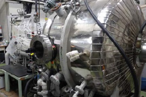
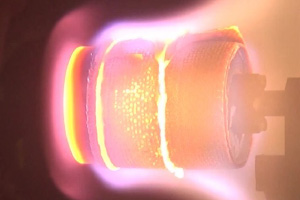
Using the 750 kW Arc-heated Wind Tunnel (*1) owned by JAXA, we conducted tests by directing high-temperature, high-speed airflow at the test specimens to simulate atmospheric re-entry conditions. By measuring temperatures during the test and comparing the test specimens before and after the test, we can understand the behavior of the materials under high-enthalpy airflow.
Evaluation Results (Phenolic CFRP)
| Material | Sample density (g/cm³) |
Test condition | Temperature | Thickness | ||||
|---|---|---|---|---|---|---|---|---|
| Heat rate (MW/m²) |
Distance (mm) |
Surface (max) (℃) |
Backside (max) (℃) |
Before test (mm) |
After test (mm) |
Δ (mm) |
||
| Phenolic CFRP | 1.54 | 3.6 | 100 | 2329 | 166 | 35.41 | 33.35 | -2.06 |
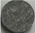
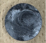
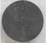
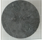
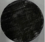
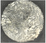
Appearance of specimen
| Before test | After test |
|---|---|
|
|
|
|
Although the material was eroded during the test, the temperature on the back side of the test specimen remained low compared to the temperature on the surface exposed to the airflow. These results suggest that phenolic CFRP, while possessing mechanical properties similar to those of general CFRP, has the potential to function as thermal protection via the ablation mechanism when exposed to high-enthalpy airflow.
Evaluation Results (C/C Composite, C/SiC Composite and “C/C Composite + Zr/Ti Alloy”)
| Material | Sample density (g/cm³) |
Test condition | Temperature surface (℃) |
Thickness | |||
|---|---|---|---|---|---|---|---|
| Heat rate (MW/m²) |
Distance (mm) |
Before test (mm) |
After test (mm) |
Δ (mm) |
|||
| C/C composite | 1.69 | 4.7 | 100 | 2235 | 8.08 | 7.32 | -0.76 |
| C/SiC composite | 2.38 | 3.6 | 100 | 1544 | 29.65 | 29.87 | 0.22 |
| C/SiC composite | 2.41 | 6.1 | 80 | 1842 | 29.99 | 30.12 | 0.13 |
| C/C composite + Zr/Ti alloy | 2.34 | 4.7 | 100 | 2412 | 9.77 | 9.86 | 0.09 |
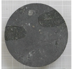
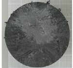
Appearance of specimen
| Before test | After test | |
|---|---|---|
| C/C composite |
|
|
| C/SiC composite Heat rate 3.6 MW/m² |
|
|
| C/SiC composite Heat rate 6.1 MW/m² |
|
|
| C/C composite + Zr/Ti alloy |
|
|
Even under conditions where C/C Composites—traditionally used as heat-resistant materials—were eroded, the C/SiC Composites and “C/C Composites + Zr/Ti Alloy” showed no erosion. This demonstrates their potential for use in heat shields and other applications under more severe environmental conditions.
Furthermore, since the “C/C Composite + Zr/Ti Alloy” did not erode even at surface temperatures exceeding 2400°C, research is currently underway to utilize it not only for satellite and space applications but also as a component for nuclear fusion reactors.
Reference information
- ※1 750 kW Arc-heated Wind Tunnel
- Phenolic CFRP Evaluation Poster Material
- C/SiC Composite Evaluation Poster Material
- C/C Composite + Zr/Ti Alloy Evaluation Poster Material
- Product : Carbon fiber reinforced plastics (CFRP) molded products
- Product : C/C composite and C/SiC composite
- News Release: Starting Joint Research to Produce Novel Carbon Composite Materials for Fusion Reactor Divertor